In-Flight Rotorcraft Acoustics Program
IN-FLIGHT ROTORCRAFT ACOUSTICS PROGRAM
Experimental Techniques

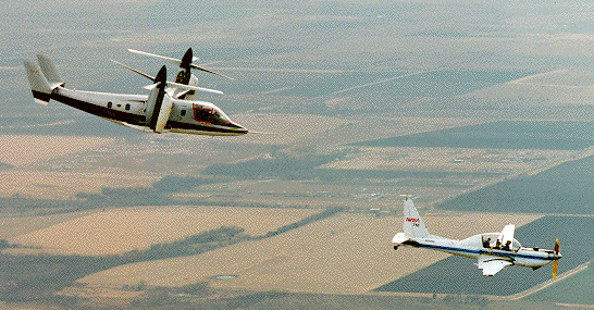
The most recent IRAP test was with the XV-15 tiltrotor.
Why Flight Test?
Wind-tunnel tests provide precise, repeatable control of rotor operating conditions, but accurate noise measurements are difficult for several reasons:
1. Wall effects prevent the rotor wake from developing exactly as it does in free flight. This is crucial because an important contributor to rotor noise is the interaction between the rotor and its own wake (such as blade-vortex interaction).
2. In many wind-tunnel tests, the rotor test stand is not the same shape as the helicopter fuselage, hence aerodynamic interference between the test stand and rotor is different than in flight.
3. The wind-tunnel walls cause reflections that may corrupt the acoustic signals.
4. The wind tunnel has its own background noise, caused by the wind-tunnel drive and by the rotor test stand. (The YO-3A aircraft is actually quieter than many wind tunnels.)
5. The wind tunnel turbulence level is rarely the same as in flight.
6. The rotor is frequently trimmed differently in a wind-tunnel test than in flight.

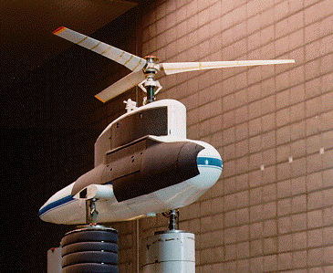
The XV-15 rotor on the Rotor Test Apparatus (RTA).
Methods of reducing or compensating for these effects are available, but they are not always effective and remain under development. It is important to verify that the wind-tunnel data match flight data. One approach is to fly the rotorcraft over a microphone placed on the ground, so that it measures what a human hears. However, such data are non-steady because the distance and angle from the rotor to the microphone is constantly changing, whereas in a wind tunnel the geometry is fixed. Hence, averaged fly-over data must be corrected before comparisons can be made with wind-tunnel data.
There remains a need to validate the data-correction methods. The solution used by IRAP is to put microphones on a quiet airplane flying in formation with the rotorcraft. The measurement geometry can be matched to that in the wind tunnel, permitting direct comparison with wind-tunnel data. NASA's YO-3A acoustics research aircraft was modified explicitly for this purpose. Once the wind-tunnel data for a few critical test conditions are verified with flight test data, the rotor is tested in the wind tunnel over a wide variety of operating conditions with greater confidence in the noise measurements.

Flight vs. Wind-Tunnel Tests
Test conditions are controlled differently in flight than they are in wind tunnels. Some parameters that are easily controlled in flight cannot be controlled at all in a wind tunnel, and vice versa. For IRAP, flight test conditions must be closely comparable to wind tunnel test conditions. The major issues involved in simultaneously planning flight and wind tunnel tests are briefly discussed here.
Airspeed, rotor speed, and rotor thrust are easily controlled in a wind tunnel, and can be set to values not possible in flight. For IRAP flights, the lower airspeed limit is set by YO-3A stall (obviously, helicopters have no lower limit). Some helicopters, and all tiltrotors, are actually faster than the YO-3A, so the upper limit is often set by the YO-3A's flight envelope. The upper limit has not been important to date because BVI noise is typically loudest during approach to landing, when airspeed is low.
Most helicopters can easily adjust their rotor speed, but only within a very narrow range. Thrust must always match weight -- adjusted for download, drag, etc. -- in trimmed flight, and the thrust will vary as fuel is burned off. Tiltrotors and compound helicopters have wings that share lift with the rotor, but the total lift must still match the total weight in unaccelerated flight. In contrast, a rotor in a wind tunnel need not produce any particular amount of thrust nor turn at flight rotor speed.
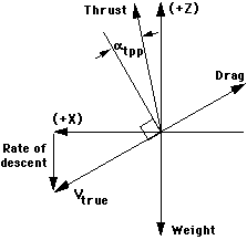
Forces acting on a rotor. In trimmed flight, thrust must balance the vector sum of drag and weight; this determines the tip-path-plane angle. (Vectors are not to scale.) (See also Signor, et al., 1994.)
Altitude is readily controlled in flight, although altitude changes may require considerable time. IRAP test altitudes range from about 2000 to 10,000 feet; a reduced range is normal for reasons of safety and efficiency. Very few wind tunnels, however, can control altitude (i.e., pressure): the effective altitude is usually determined by the weather -- temperature and barometric pressure -- at the time of the test. Also, the effective altitude in a wind tunnel may change during the test as the air in the circuit heats up.
Fortunately, these four parameters -- airspeed, altitude, rotor speed, and thrust -- can be chosen such that flight and wind-tunnel test conditions match the physical flow phenomena of interest, thereby allowing the data to be directly compared. Instead of matching rotor speed, tip Mach number is matched, which automatically compensates for temperature. Instead of matching airspeed, advance ratio -- the ratio of forward speed to rotor tip speed -- is matched at the chosen tip Mach number. Instead of matching thrust and altitude, thrust coefficient is matched; the thrust coefficient is the thrust adjusted for density, rotor speed and rotor disk area. In flight, altitude is adjusted to compensate for fuel burn-off; in the wind tunnel, thrust is adjusted to compensate for temperature.
Rate of descent -- or descent angle -- is easily adjusted in flight. The upper limit is set by YO-3A handling qualities: 1000 feet per minute is roughly the maximum practical value. In the wind tunnel, rate of descent is simulated by tilting the rotor test stand backwards, so that the airflow has an upwards component relative to the rotor.
For acoustics measurements, control -- or at least knowledge -- of rotor tip path plane is important. Tip-path-plane angle is the angle between the rotor disk and the resultant velocity vector; hence, it is the effective angle of attack of the rotor as a whole. In flight, the angle is determined by trim and cannot be independently controlled. In a wind tunnel, directly controlling tip path plane is not always practical; the rotor is usually trimmed to zero flapping. If set to zero flapping, or otherwise limited by loads or controls setup, tip path plane would then be determined by the test-stand pitch chosen to simulate rate of descent.
Note that tiltrotors are a special case because pylon (or rotor nacelle) tilt changes the tip path plane. Pylon tilt also affects trim, so it is not a completely independent control. There is no equivalent adjustment, independent of shaft tilt, for an isolated-rotor test in a wind tunnel. Only purpose-built tiltrotor models have both pylon tilt and shaft tilt.
Another test parameter important for IRAP is microphone angle: the angle between the rotor hub and the microphone measuring BVI noise. In flight, the achievable angle is limited by visibility: the helicopter pilots following the YO-3A must be able to clearly see the YO-3A in order to safely maintain formation. At very high angles, the YO-3A is not visible over the helicopter instrument panel. Below that limit, the microphone angle is easily adjusted in flight by adjusting the relative positions of the two aircraft.
In the wind tunnel, microphone position is typically fixed, hence the angle to the rotor varies slightly with test-stand pitch. There is no practical barrier to remotely controlling the microphone position in the vertical (X-Z) plane to compensate, but this has yet to be implemented for any IRAP-related test.
The final test parameter to be considered is microphone distance: the distance from the center of the rotor hub to the microphone. In flight, the separation distance is typically set at two or three rotor diameters and is measured by a laser rangefinder. Although workload is high, pilots can control formation distance to within a few feet.
In the wind tunnel, the microphone is usually fixed and the distance varies slightly with test-stand pitch. The distance could in principle be controlled with an adjustable microphone mount, but this has not yet been done for purposes of matching IRAP data. (Note that acoustic traverses are commonly used in wind tunnels to move one or more microphones in the horizontal plane, thereby scanning a large area under a rotor. These changes in microphone position are much larger than what would be required to compensate for test-stand pitch.)
Related Publications:
Signor, D. B., Watts, M. E., Hernandez, F. J., and Felker, F. F., "Blade-Vortex Interaction Noise: A Comparison of In-Flight, Full-Scale, and Small-Scale Measurements." American Helicopter Society Aeromechanics Specialists Conference, San Francisco, CA, January 1994.
See also the references page.
Point of Contact:
C. W. Acree
NASA Ames Research Center
Moffett Field CA 94035-1000