
ROTOR DATA CORRELATION PROJECT
Wind tunnel test measurements, flight test measurements, and analytical prediction play a key role in the development of new rotor systems. Tests are typically performed using a range of rotor system sizes and wind tunnel test facilities. To assure the accuracy of wind tunnel testing methodology, a validation study used test results from model- and full-scale tests in comparison with flight test data under the Rotor Data Correlation Task of the U.S. Army/German Memorandum of Understanding on Cooperative Research in the Field of Helicopter Aeromechanics. This comparison determined of the ability to accurately predict helicopter flight behavior from wind tunnel experiments and the influence of the test facility on these results. Experimental data from a series of wind tunnel tests, including both model- and full-scale experiments, were studied to determine the extent to which wind tunnel test results can be used to predict flight behavior.
A series of flight tests was conducted at the Deutsche Forschungsanstalt für Luft- und Raumfahrt e.V. (DLR) in the spring and autumn of 1992 using a BO-105 helicopter in Braunschweig, Germany. These flights were conducted at various altitudes and speeds for steady level flight. Upon completion of the flight test program, the data were reduced and evaluated to identify a series of test conditions for the full-scale NASA 40- by 80-Foot Wind Tunnel test program, which was conducted during the winter of 1993 and a 40 percent scale-model test in the German-Dutch Wind Tunnel (DNW) that was conducted in February 1995.
Flight Testing
 The primary task for the flight test program was to define test points for a wind tunnel test in the 40- by 80-Foot Wind Tunnel and subsequent testing of a 40 percent scale-model in the DNW. In conducting the flight tests, careful attention to the establishment of a flight condition was essential. Post test data evaluation was also very important to determine the test conditions for the subsequent wind tunnel tests.
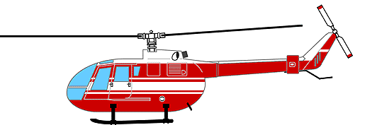
The BO-105 aircraft used in the flight test program is one of two BO-105 helicopters at the DLR Institute of Flight Mechanics in Braunschweig, Germany. The BO-105 is 5000 lb gross weight aircraft with a maximum sea level speed of 145 knots. Included on the aircraft was an onboard data acquisition system with a sampling rate of 200 Hz. Data were digitized and stored on a removable hard disk during the flight. The removable hard disk was later used to transfer data to another computer system for post-processing.
The BO-105 flight tests were performed for level flight only at three different flight (altitude) levels. To get a wide data base for application to the wind tunnel rotor tests, the flight tests were performed for the following conditions; 1) horizontal speed range from hover (OGE) to maximum speed with a stepsize of 10 knots, 2) three different altitudes, 3) two center-of-gravity (c/g) positions (baseline position, and 121 lb mass at the tail), and 4) three different main rotor RPM's in hover (95 percent, 100 percent, and 102 percent).
Full-Scale Wind Tunnel Testing
 The primary objective of this test program was to create a data base for full-scale hingeless rotor performance and structural blade loads over a wide range of rotor thrusts and tunnel velocity. A secondary objective was to investigate the ability to match flight test measurements in the wind tunnel based on the results of a BO-105 flight test program, conducted by the DLR in Braunschweig, Germany. Rotor performance and structural blade loads data for tunnel velocities from hover to 170 knots and thrust coefficients (CT/sigma) from 0.0 to 0.12 were acquired in the NASA Ames 40- by 80-Foot Wind Tunnel. A limited amount of data were acquired for simulated steady level flight conditions (CT/sigma = 0.071 and 0.089) from 40 knots to 130 knots.
The test hardware for the full-scale testing included the NASA Ames Rotor Test Apparatus (RTA) and a BO-105 rotor system in the 40- by 80-Foot Wind Tunnel. The BO-105 helicopter rotor system is a four-bladed, soft inplane hingeless rotor with constant chord (0.886 ft), -8 deg linear twist, and a NACA 23012 cambered airfoil. The rotor radius is 16.11 ft; rotor solidity is 0.07. The rotor hub has 2.5 deg of built-in coning and zero droop or sweep of the blade outboard of the pitch bearing.
Model-Scale Testing
 The primary objective of the 40 percent scale-model test was aimed at answering questions regarding rotor scaling effects and the influence of the tunnel walls on rotor performance and blade loads. The DNW test program was structured in a manner that direct comparisons between model-scale and flight test results could be made by trimming to measured flight test hub moments, as well as direct comparisons of model-scale results with 40- by 80- results for both hub moment and minimized blade flap bending trim conditions. The DNW test program was also structured so that the same test conditions were repeated in nearly all the available test sections to identify and understand the influence of the tunnel walls on measured rotor performance and blade loads. Testing was conducted in the 6- by 6-meter, 8- by 6-meter (open and closed slots), 9.5- by 9.5-meter, and the 8- by 6-meter Open Jet test sections.
The test hardware for the model-scale testing included the DLR rotor test stand with a 40 percent scale-model of a BO-105 rotor system and a scaled BO-105 fuselage on its own balance. The types of measurements that were made in this test program include rotor forces and moments, fuselage forces and moments, blade bending and torsional moments, fuselage pressures (static), and tunnel wall pressures (static).
Results
Results from the full-scale rotor test in the NASA Ames 40- by 80-Foot Wind Tunnel and the DLR flight test of a BO-105 helicopter have been correlated. Rotor hub and blade loads were obtained over a range of advance ratios from 0.1 to 0.34 for a nominal rotor thrust of 5000 lbs. (CT/Sigma = 0.07). Good correlation of measured blade root flap bending moments in the wind tunnel with flight test measurements is shown when the rotor is trimmed to measured flight test hub pitch and roll moments. Analytical results using the CAMRAD/JA (Comprehensive Analytical Model of Rotorcraft Aerodynamics and Dynamics, Johnson Aeronautics) analysis show good correlation for isolated rotor hub moment trim. Comparisons of wind tunnel, flight test, and analytical results of rotor blade flap bending at an inboard radial station at a nominal rotor thrust of 5000 lbs at an advance ratio of 0.197 are shown in figure 1.
Figure 1. Comparison of measured wind tunnel and flight test rotor flap bending with analytical results at an advance ratio of 0.197 and 1-g thrust.
Related Publications:
If needed: Download Acrobat Reader
Peterson, R. L., Maier, T., Langer, H. J., and Tränapp, N., "Correlation of Wind Tunnel and Flight Test Results of a Full-Scale Hingeless Rotor," Proceedings of the American Helicopter Society Aeromechanics Specialist Conference, San Francisco, CA, January 1994. Paper No. 2.2.
Peterson, R. L., "Full-Scale Hingeless Rotor Performance and Loads," NASA TM 110356, June 1995. Download
Langer, H. -J., Peterson, R. L. and Maier T., "An Experimental Evaluation Of Wind Tunnel Wall Correction Methods For Helicopter Performance," Proceedings of the 52nd Annual Forum of the American Helicopter Society, June 1996.
Peterson, R. L. and Nguyen, K., "Aeroelastic Stability of a Full-Scale Hingeless Rotor," NASA TM 110417, August 1996. Download
Point of Contact:
Thomas Norman
NASA Ames Research Center
Moffett Field CA 94035-1000