
ROTOR DESIGN OPTIONS FOR WHIRL FLUTTER
BACKGROUND
Coupled wing/rotor whirl-mode aeroelastic instability is the major barrier to increasing tiltrotor speeds. This research investigated the unusually simple approach of adjusting the chordwise positions of the rotor blade aerodynamic center and center of gravity to improve the stability boundary of the full aircraft. The XV-15 tiltrotor research aircraft was modeled with the CAMRAD II rotorcraft analysis program; the model was then modified to simulate a thinner wing, which had lower drag but also a lower stability boundary. A systematic investigation of rotor modifications was defined to study their effects on whirl flutter, using the thin-wing XV-15 as a baseline against which to compare the results.
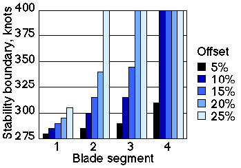
Figure 1. Whirl-mode stability boundaries for aerodynamic-center offsets.
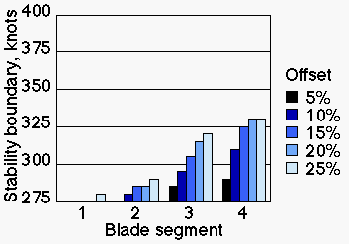
Figure 2. Whirl-mode stability boundaries for center-of-gravity offsets.
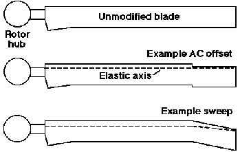
Figure 3. Example blade planforms.
Sequence 1
Sequence 2
ACCOMPLISHMENTS
Over 900 cases were run to map out a full set of parametric variations of blade section aerodynamic center (AC) and center of gravity (CG). Figures 1 and 2 summarize the results of shifting the AC and CG in discrete steps of 5% of tip chord, distributed among four radial segments (Figure 3). Small rearward offsets of the AC created large increases in the stability boundary, in some cases by over 100 knots. The effect grew progressively stronger as the offsets were shifted outboard. Forward offsets of the CG had similar effects, but the maximum improvement was limited to 55 knots. The results were published in "Rotor Design for Whirl Flutter: An Examination of Options for Improving Tiltrotor Aeroelastic Stability Margins" and presented at the 1999 American Helicopter Society Annual Forum. If needed: Download Acrobat Reader
The research has recently been extended to include swept blades (Figure 3), which give benefits similar to stepped offsets, but for a much more practical blade configuration. Also under study are the effects of control-system (pitch) stiffness and pitch-flap coupling (delta-3).
Development of a V-22 model for CAMRAD II is underway. It will serve as a baseline for future rotor studies, which will apply the same design techniques summarized here to the larger and more advanced V-22 rotor.
DEMONSTRATION MOVIES
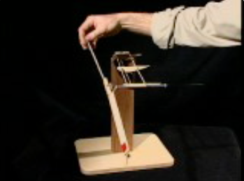
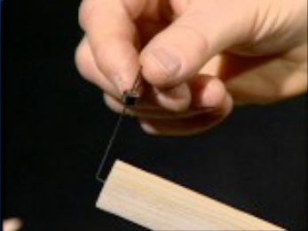
To demonstrate the concept, a very simple, unpowered, table-top model of a wing and rotor was built of balsa wood and driven by an ordinary box fan. The wing was a ladder-frame structure with no aero--dynamic shell, and the rotor was a two-bladed, teetering design. The 17-in diameter rotor had a weight extended ahead of the leading edge of each tip. A pair of QuickTime movies demonstrate the dramatic improvement in stability achieved by moving the tip weight forwards. The movies are shown below in short version and may be downloaded in long version.
Related Publications:
Acree, C. W., Peyran, R. J. and Johnson, W., "Rotor Design for Whirl Flutter: An Examination of Options for Improving Tiltrotor Aeroelastic Stability Margins," Proceedings of the 55th Annual Forum of the American Helicopter Society, May 1999. Download Paper If needed: Download Acrobat Reader
Point of Contact:
Dr Wayne Johnson
NASA Ames Research Center
Moffett Field CA 94035-1000