
FULL-SCALE S-76 ROTOR RESEARCH IN THE
80- BY 120-FOOT WIND TUNNEL
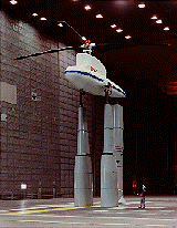 The Aeromechanics Branch at Ames Research Center conducted their first rotor test in the NASA Ames 80- by 120-Foot Wind Tunnel with a newly acquired Sikorsky S-76 rotor hub/blades system mounted to the recently modified Rotor Test Apparatus (RTA) in early 1992. This wind tunnel test generated a unique and extensive data base covering a wide range of rotor shaft angles-of-attack and thrust conditions from 0 to 100 kt.
The objectives of this wind tunnel test were to (1) evaluate the capability of the 80x120 test section as a hover facility; (2) acquire forward flight rotor performance data for comparison with analytical results; (3) acquire S-76 forward flight rotor performance data in the 80x120 wind tunnel to compare with existing and future 40x80 data for evaluation of differences and similarities between the two full-scale wind tunnel facilities, (4) evaluate rotor inflow and wake effects (varied by varying tunnel speed, shaft angle, and thrust condition) on wind tunnel test section wall and floor pressures; (5) establish a criteria for the definition of flow breakdown (point where wall corrections are no longer valid) for this given size rotor and wind tunnel cross-sectional area; and (6) evaluate the wide-field shadowgraph technique for visualizing full-scale rotor wakes.
Rotor Performance
Hover rotor performance data were compared with calculations based on momentum theory and previously acquired data from other test facilities to evaluate the capabilities of this wind tunnel as a hover facility. Forward flight rotor performance data were compared with the calculations from a comprehensive rotorcraft analysis, CAMRAD/JA, to evaluate the analytical modeling in the 0 to 100 kt speed range. Rotor performance data were also compared with previously acquired S-76 full-scale data from a test in the Ames 40- by 80-Foot Wind Tunnel to evaluate similarities and differences between the two facilities. Hover performance data show significant variations depending on the test configuration. Comparisons with theoretical predictions and other test data suggest that hover testing at an outdoor facility in absence of ground effect is required to make a final determination of the absolute accuracy of the hover data acquired in the 80x120. CAMRAD/JA calculations show good correlation with propulsive force data and a consistent level of overestimation of rotor power throughout the thrust and rotor shaft angle-of-attack envelope for a velocity range of 40 to 100 kt; below 40 kt, CAMRAD/JA power calculations diverge from the data. A comparison of the 80x120 data with data from a previous 40x80 wind tunnel test for 60 to 100 kt velocity range shows good correlation with rotor power and propulsive force data, except at the higher rotor shaft angles where there are some differences in rotor power. Results from the two S-76 wind tunnel tests suggest that the wind tunnel wall corrections should not be used for rotors operating in a nominal thrust range with rotor diameters up to 55% of the wind tunnel test section width, for advance ratio „ 0.150, in either the 40x80 or 80x120.
A sample of rotor performance data is shown in Figure 1. Figure 1 shows the correlation of S-76 rotor performance data with a rotorcraft prediction code called CAMRAD/JA.
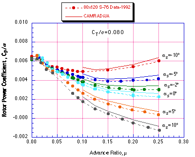
Figure 1. The effects of advance ratio and as on measured and predicted rotor power, CT/sigma=0.080, MTIP=0.605.
Tunnel Wall Interaction with Rotor
Three configurations were tested: empty tunnel; test stand body (fuselage) and support system; and, fuselage and support system with rotor installed. Empty tunnel wall pressure data are evaluated as a function of tunnel speed to understand the baseline characteristics. Aerodynamic interaction effects between the fuselage and the walls of the tunnel are investigated by comparing wall, ceiling, and floor pressures for various tunnel velocities and fuselage angles-of-attack. Aerodynamic interaction effects between the rotor and the walls of the tunnel are also investigated by comparing wall, ceiling, and floor pressures for various rotor shaft angles, rotor thrust conditions, and tunnel velocities. Empty tunnel wall pressure data show good repeatability and are not affected by tunnel speed. In addition, the tunnel wall pressure profiles are not affected by the presence of the fuselage apart from a pressure shift. Results do indicate that the tunnel wall pressure profiles are affected by the presence of the rotor. Significant changes in the wall, ceiling, and floor pressure profiles occur with changing tunnel speeds for constant rotor thrust and shaft angle conditions. Significant changes were also observed when varying rotor thrust or rotor shaft angle-of-attack. Other results indicate that dynamic rotor loads and blade motion are influenced by the presence of the tunnel walls at very low tunnel velocity and, together with the wall pressure data, provide a good indication of flow breakdown.
A sample of tunnel wall pressures with the rotor system and test stand present is shown in Figure 2. Figure 2 shows that the S-76 rotor system and test stand do have an effect on tunnel wall pressures only at very low tunnel speeds.
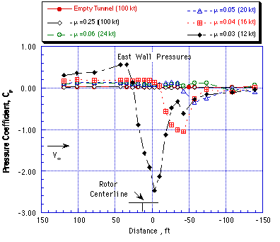
Figure 2. Effect of advance ratio on tunnel east wall pressures, shaft angle=-2.0 degrees, CT/sigma=0.100
Shadowgraph Flow Visualization Technique
Hover, low-speed forward flight and descent operating conditions were studied. Preliminary results are very promising with rotor wake tip vortices visible up to an advance ratio of 0.25. In addition, many details of the rotor wake were visible, including tip vortex roll-up, inboard wake vorticity, and flow unsteadiness due to test section recirculation effects in hover. Shadowgraphs of blade/vortex interactions were also acquired. Simultaneous top and side view shadowgraphs of the rotor wake were acquired by a newly developed synchronized digital imaging system. The imaging system proved to be a highly successful tool which made real-time examination of selected regions of the rotor wake possible.
A sample of two simultaneous shadowgraph views of the rotor wake is shown in Figure 3. Figure 3 shows the side view and the top view of the tip vortex trajectories and apparent blade-vortex interaction on the advancing side of the rotor disk.
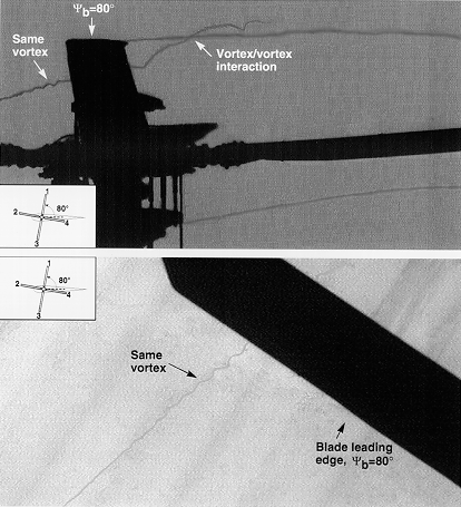
Figure 3. These two images represent two simultaneous projections (top and side views) of the rotor wake interactions. These images were captured by externally triggered CID cameras and frame grabber cards.
Related Publications:
If needed: Download Acrobat Reader
Shinoda, P. M. and Johnson, W., "Performance Results from a Test of an S-76 Rotor in the NASA Ames 80- by 120-Foot Wind Tunnel," AIAA 11th Applied Aerodynamics Conference, Monterey, CA, August 1993. AIAA-93-3414. Download
Shinoda, P. M., "Wall Interaction Effects for a Full-Scale Helicopter Rotor in the NASA Ames 80- by 120-Foot Wind Tunnel," AGARD 73rd Fluid Dynamics Panel Meeting and Symposium, Brussels, Belgium, October 1993. Paper Number 20.
Swanson, A. A., "Application of the Shadowgraph Flow Visualization Technique to a Full-Scale Helicopter Rotor in Hover and Forward Flight," AIAA Applied Aerodynamics Conference, Monterey, CA, August 1993. AIAA-93-3411. Download
Points of Contact:
Thomas Norman
NASA Ames Research Center
Moffett Field CA 94035-1000