
Tiltrotor Aeroacoustic Model Summary
Project Details | Tram Organization Chart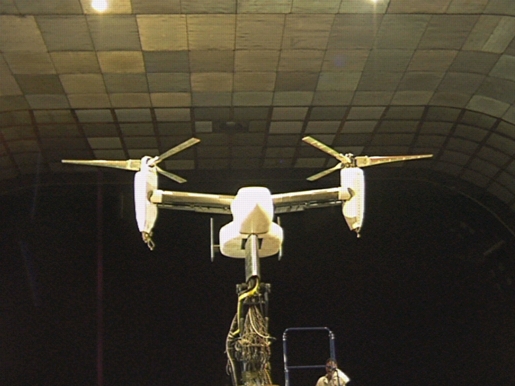
Introduction:
Tiltrotor aircraft are unique and valuable because they can takeoff and land like a helicopter, but fly fast like an airplane. They represent a new class of subsonic air transport for military and civil aviation.
The Civil Tiltrotor Development Advisory Committee (CTRDAC) studied the technical feasibility and financial viability of developing a civil tiltrotor aircraft. In their report to Congress, the committee concluded that the civil tiltrotor concept is technically feasible, a market exists, and the civil tiltrotor has the potential of relieving congestion at major airports. Tiltrotor noise levels, however, can be significant enough to compromise their applications.
NASA's goals are to understand and reduce the technology barriers for introducing civil tiltrotor aircraft. Through the Advanced Subsonic Transport and the Aviation Systems Capacity programs, NASA initiated the Short Haul Civil Tiltrotor, (SH (CT)), program to address concerns about tiltrotor noise, as well as operating efficiency and safety, for civil applications. To accomplish these noise reduction goals, wind tunnel testing of moderate to large-scale tiltrotor models is required. Together, NASA and the US Army have developed a new tiltrotor aeroacoustic research facility, the Tilt Rotor Aeroacoustic Model (TRAM). The TRAM program was initiated to provide the data necessary to confirm performance, aeroacoustic prediction methods, and to investigate advanced low noise tiltrotor technologies.
Selection of a Baseline Tiltrotor aircraft:
The TRAM baseline rotors and airframe are based on 1/4 scale of a Bell/Boeing V-22 Osprey tiltrotor aircraft, which is being developed for the U.S. Marines/Navy and the U.S. Air Force. Selection of the V-22 as a baseline was dictated by three primary considerations. First, the gross weight of the V-22 is close to the proposed 40 passenger civil tiltrotor studied by the CTRDAC and others. The civil tiltrotor performance characteristics may therefore be similar to those of the V-22. Second, as the first production tiltrotor aircraft, many V-22Õs will soon be flying and providing valuable operational data in the years ahead. This will create opportunities for comparisons between wind tunnel test results and full-scale flight vehicle data. Third, the 1/4-scale model size was selected with consideration of the test section size of the two facilities where TRAM would primarily be tested.
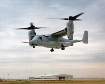
Figure 1: V-22 Osprey
TRAM was originally configured as an isolated rotor, before complete assembly as a full-span dual rotor aircraft model. Conducting an isolated rotor test proved to be valuable risk reduction for the testing the full-span TRAM Ð as well as providing an excellent complementary data set enabling assessments of the interactional aerodynamics and acoustics of tiltrotor aircraft. The isolated rotor was tested in the open-jet test section of the Duits-Nederlandse Wind Tunnel (DNW). The full-span dual rotor model is currently being tested in the 40 by 80 foot test section of the National Full-scale Aerodynamic Complex (NFAC) at NASA Ames Research Center 40-by 80-Foot Wind Tunnel.
Rotorcraft aeroacoustics is the generation of noise from aerodynamic interactions on rotor blades and consists of rotational, broadband, impulsive, and, most significant, blade-vortex interaction, or BVI noise. Each individual noise type can be measured and identified by rotor wind tunnel experiments. This experimental data can provide pilots and engineers with the necessary information to modify the flight operations of tiltrotor aircraft -- and/or develop new rotor designs -- to help minimize noise.
Blade vortex interaction (BVI) noise is a very loud sound, usually dominating other rotorcraft noise sources. It occurs in certain flight conditions when a rotor blade intercepts (or comes in close proximity to) the vortex shed by a preceding blade. This usually occurs when a tiltrotor aircraft is in descent. When tiltrotor (prop)rotors operate in low speed, partial power, descent flight conditions, the rotor wake (and blade tip vortices) stay in close proximity to the rotor disk plane, causing strong blade vortex interactions. Close passage of a blade to a rotor wake vortex results in variation in induced velocity at the blade surface which causes large, rapid fluctuations in pressure on the blade and generates impulsive sound. The strength of blade vortex interaction is governed by several parameters such as:
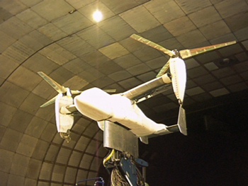
Figure 2: TRAM in the 40- by 80-Foot Wind Tunnel Test Section
• Local strength of the tip vortex
• Core size of the tip vortex
• Local interaction angle between the blade and the vortex line
• Vertical separation distance between the vortex and the blade
BVI can be easily identified in the time history by a sharp triangular positive pressure pulse as shown below.
The Test Model:
The full-span TRAM test model consists of a steel and aluminum frame with fiberglass skins, a rigid steel wing, an aluminum empennage, and dual composite (fiberglass and graphite epoxy) rotors. Two high-speed electric motors are housed in the fuselage and a series of gearboxes and drive shafts transmit power through the wing into transmissions in the nacelles. The motors and drive train are designed to deliver up to 300 HP to each rotor. The wing was not designed to be aeroelastically scaled with respect to the V-22 aircraft. The model structure is designed for testing up to 300 knots, the maximum speed of NFAC. It is also equipped with remotely adjustable flaperons and elevator. The rudders are ground-adjustable, but are nominally zero degrees for most of the wind tunnel testing. The wind tunnel mounting allows for angle-of-attack control. Nacelle tilt settings on the full-span TRAM are currently ground-adjustable only. In addition to the model hardware, health and SOF monitoring systems, utility and fixed-wing control console workstations were developed to support efficient and safe wind tunnel testing.
Measurements:
Numerous measurements are being made on the Full Span TRAM to meet NASA's research goals. Over 700 data, health monitoring and Safety-of-Flight (SOF) instrumentation channels are incorporated into this model. These include rotor structural loads, balance loads, wing pressures, rotor airloads, acoustics, flow visualization, and flow velocity measurements. Below is a brief description of each.
1. 2. 1. Blade Structural Loads: These are strain gauges on the Safety of Flight (SOF) blades that measure flap, chord, and torsional bending. These blade measurements are required during flight to monitor the health of the blades. The blades are dynamically scaled and the blade structural data will be used for tiltrotor dynamic research and validation of comprehensive codes such as CAMRAD II. Blade dynamics, and elastic deflections, can have an important influence on rotor acoustics; this influence on tiltrotor acoustics is probably not as critical, though, as that for helicopter noise predictions because tiltrotor prop-rotors are more structurally rigid than helicopter rotors which also have less twist.
3. 4. 2. Balance loads: There are three balances on the FS TRAM, a right and left rotor balance, and a fuselage balance. These are required for SOF monitoring, setting the test condition (such as rotor thrust), and performance measurements (such as lift and drag). The three balances allow for unique vehicle studies such as determination of the lift sharing between the rotors and the wings in forward flight. This tiltrotor performance data set will be unique because it will be acquired at a higher accuracy, with more comprehensive and complementary measurements, and steadier test conditions than in previous tiltrotor tests.
5. 6. 3. Blade airloads: There are 149 dynamic pressure transducers distributed between two right-hand blades. These are the same blades that were tested at the DNW in the isolated rotor configuration. These blades are the first set of tiltrotor blades to have dynamic pressure instrumentation and these measurements provide valuable tiltrotor blade aerodynamic information, such as blade tip loading, which has not been previously available. Comparing isolated rotor data to full-span data will allow investigation of how the aerodynamics of a rotor is changed by the presence of the wing and the second rotor. The airloads data will also help researchers confirm the generation and location of dual vortices trailed by tiltrotor blades on the advancing side of the rotor in helicopter-mode forward-flight, which is vital for the improvement of tiltrotor computational codes. U.S. Rotorcraft Industry has a strong interest and need for this data for code validation. For example, Sikorsky Helicopters alone uses three codes (TRAC by NASA Langley, FreeWake by Egolf, and the Maryland FreeWake by Bagai) that would benefit from the FS TRAM database.
7. 8. 4. Acoustics: Acoustic measurements will be obtained in a plane 5 meters (1.73 rotor diameters) below the rotor via 12 microphones distributed across two traverses. Noise measurements (along with blade airloads) can be used to validate acoustic prediction codes and as a baseline for comparison to other designs. Acoustic measurements on the FS TRAM can be compared to the DNW, and the three BART tests conducted at the Langley 14' x 22' wind tunnel (NASA's V-22, Sikorsky VDTR and Boeing 5-bladed). Blade vortex interaction (BVI) noise generation and directionality for a tiltrotor can also be investigated.
9. 10. 5. Wind pressures: There are 185 static pressure ports on the left wing and flaps. These gauges will provide data for wing lift, stall, rotor flow, and rotor-wing interactions such as rotor download. Boeing - Philadelphia has expressed interest in download reduction studies such as advanced flaperon designs. Bell Helicopters requested pressure ports added to the fuselage (not currently installed) to study the fountain flow between the two rotors.
11. 12. 6. LLS Flow Visualization: Laser light sheet (LLS) flow visualization will be used with the FS TRAM to observe dual vortex formation for a BVI condition at different wake ages. The dual-vortices greatly complicate the wake and understanding the evolution, convection, and dissipation of the rotor wake is critical to prediction of BVI noise.
13. 14. 7. PIV wake measurements: Particle Image Velocimetry (PIV) will be used to measure the vortex velocity field for the dual vortex visualized in LLS. This quantitative information will be used to improve computational codes attempting to model the tiltrotor wakes. Although these flow measurement techniques are in their infancy and techniques still need refinement, the benefits of the data are clear. Just a few computational codes that could profit from these measurements (and all of the TRAM data) include TRAC, CAMRAD II, Bell's COPTER, Boeing-Philadelphia's TECH2, Univ. of Maryland's UMARC, and Langley's Free Wake.
15.
The tip vortex structure has a significant impact on the rotor BVI noise and, therefore, passive blade tip modifications have the potential to alter the tip vortex structure and thus reduce noise. Clearly, however, further gains in rotorcraft noise reduction need to be made.
Conclusion:
The TRAM Project will enable new insights into the fundamental aeroacoustics of prop-rotors and tiltrotor aircraft, leading to improved aeroacoustic prediction methods and noise reduction techniques.
With the data collected from this test it is hoped that tiltrotor aircraft design can be refined to be successfully used as a civil transport aircraft. This would pave the tiltrotor's way into the future where the sky's the limit.
Point of Contact:
Larry Young
NASA Ames Research Center
Moffett Field CA 94035-1000
Links:
U.S. Rotorcraft Company links
Other V-22 links
- Air Force Technology Today
- Boeing's V-22 Osprey Site
- Bell Helicopter's V-22 Site
- U.S. Navy's V-22 Osprey Site
- Helicopter History V-22 Site