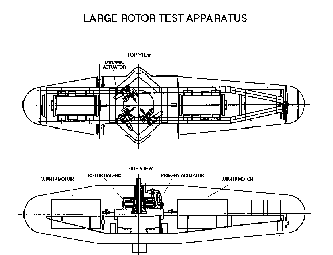
LARGE ROTOR TEST APPARATUS
DETAILED INFORMATION

The LRTA is a relatively large structure compared to past and present rigs for wind tunnel tests of rotors. The exterior configuration of the fuselage is basically a body of revolution with an overall length of 480 in and a maximum diameter of 100 in. The LRTA is designed to be supported by three struts, two forward and one aft. The length of the aft strut can be adjusted to vary the pitch angle of the apparatus (from 30 deg nose down to 15 deg nose up).
Contained within the external fairing structure is a frame designated the main support chassis which is supported by direct connections to the three struts. The chassis provides the base to which the following are directly attached: 1) a transmission, 2) two electric drive motors, which engage the transmission symmetrically from opposite sides, and 3) the fuselage fairing structure. Connection of the fairing structure to the chassis is effected by a statically determinant arrangement of six load cells. These load cells allow determination of the steady aerodynamic forces and moments on the fairing structure.
The main drive motors provide the power necessary for the rotor systems to be mounted on the LRTA. Each motor is designed to operate at a frequency range of 30 to 150 Hz with full 3000 HP capability from 120 to 150 Hz (a speed range of 2390 to 2990 rpm). (Note that maximum power output for the LRTA may be limited by NFAC MG set capabilities, rather than by the motors.) Circulating water is used for cooling and an oil-mist system is used to lubricate the motor bearings.
The rotor transmission is a self contained, two-stage-of-reduction gear box. Opposing motor shafts drive spiral bevel gear sets to perform the first stage reduction. Pinion shafts driven by the spiral bevel gears turn a helical gear set to perform the second stage reduction. The transmission is designed to transmit power from the two drive motors to the rotor output shaft and reduce the input shaft speed by a factor of 9.329:1. This gear reduction results in a maximum rotor speed for the LRTA of 320 rpm.
Seated on top of the transmission case is the Rotor Force Measurement Device (RFMD), i.e. the rotor balance. The function of the RFMD is to enable measurement of both steady and unsteady hub forces and moments. The RFMD is a large solid ring made of a 15-5 PH stainless steel custom forging. Cutouts were made in the center of the ring to leave four symmetrically placed, rectangular flexure posts. These posts are designed and gauged to measure five components of forces and moments. These include normal, axial and side forces, together with rotor pitch and roll moments to rotor thrust levels of 52,000 lb. (The sixth component, rotor torque, is measured by an instrumented flexible coupling mounted between the transmission and the rotor output shaft). The flexure post design was optimized for stiffness to eliminate balance resonance's and to provide strain levels adequate for accurate measurement. Temperature stability is provided by circulating cooling water through passages above and below the flexure posts on both the inside and outside of the balance ring. These passages provide sufficient heat transfer to provide stabilized temperatures within 2 deg F of the cooling water. Polyurethane foam encasing the perimeter of the RFMD provides thermal insulation from the surrounding environment.
The upper output unit is the final element in the transfer of power from the transmission to the rotor system. It supports the rotor and transfers rotor forces to the RFMD. The upper unit consists of a universal output shaft, upper and lower bearings, a flexible coupling adapter, and an upper output housing.
The output shaft has two distinct sections. The first section is contained inside the upper housing and is designed to withstand all combinations of LRTA design loads. The second section extends up to the rotor hub and is designed to be replaceable. This universal shaft feature allows accommodation to the requirements of any particular test rotor system. Note that this second section is normally designed to mate with an existing rotor system and, as such, may have significantly less load-carrying capability than the rest of the LRTA.
The output shaft is supported by upper and lower bearing sets. The lower bearing is designed to carry both thrust and radial loads while the upper bearing carries radial loads only. The lower end of the output shaft connects to the instrumented flexible coupling which, in turn, connects to the transmission. As mentioned earlier, this flexible coupling is designed to measure rotor torque as well as residual thrust. The final component of the upper unit, the housing, is the point of interface between the upper and lower bearing sets and is the direct carrier of loads from the rotor system to the RFMD.
Rotor control is provided through three identical actuator assemblies, each of which includes both primary and dynamic actuators. These actuator assemblies mount on an actuator plate which, in turn, mounts on the upper output unit. The primary actuators are high authority/low speed ball screw-type electric actuators and are used to provide primary control of rotor blade pitch. The primary actuation system can provide up to 11 in of stroke at a maximum rate of .335 in/sec. The dynamic actuators are low-authority high-speed rotary-hydraulic actuators and are used to provide time-varying perturbations to the non-rotating swashplate. This system can provide up to 1.1 in of travel up to a frequency of 23 Hz. Higher frequency motion is possible for smaller displacements. Control of the actuator assemblies is provided through the Primary and Dynamic Control Consoles