Tilt Rotor Test Rig
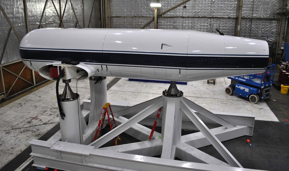
TTR as delivered to Ames (without the rotor) on the aft calibration stand. Photo Oct. 2012
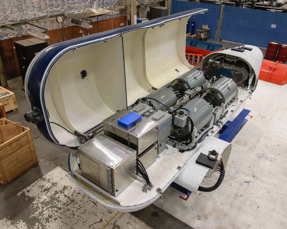
TTR as delivered to NASA, with the aerodynamic shell open. Each gray cylinder is a 1,250-hp electric motor. Photo Aug. 2012
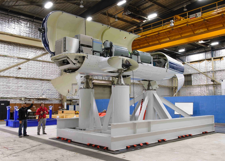
TTR on the aft calibration stand, with cowlings open. Sep. 2012
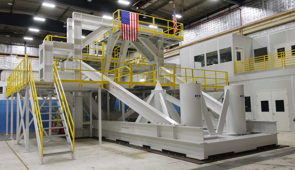
Newly completed TTR calibration rig. The rig structurally supports the TTR while balance calibration loads are applied. Photo Feb. 2013.
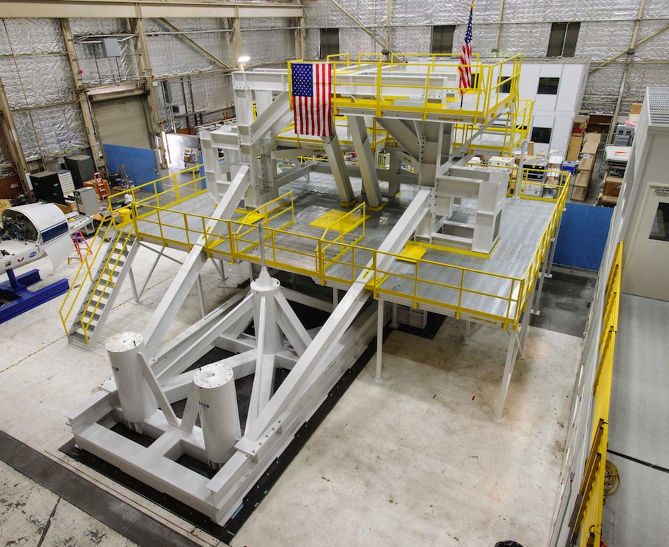
Top view of the TTR calibration rig, with forward and aft sections structurally connected. Photo Feb. 2013
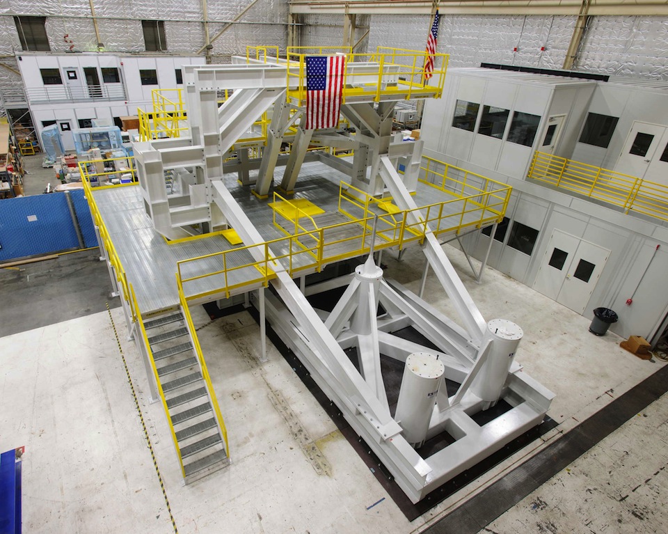
Top view of TTR calibration rig. The control room is to the right. Photo Feb. 2013
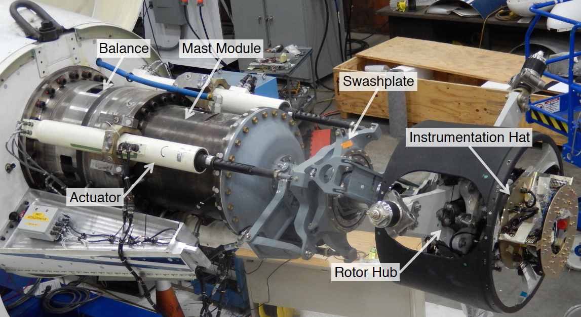
TTR balance, control actuators and rotor hub. Photo Aug. 2014
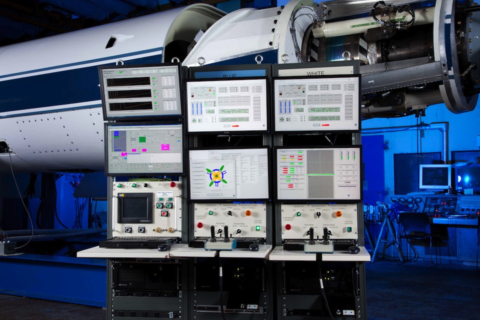
TTR Under Construction at Bell Helicopter: the paired rotor control consoles are to the center and right, and the drive control monitoring system is to the left. Photo March 2012
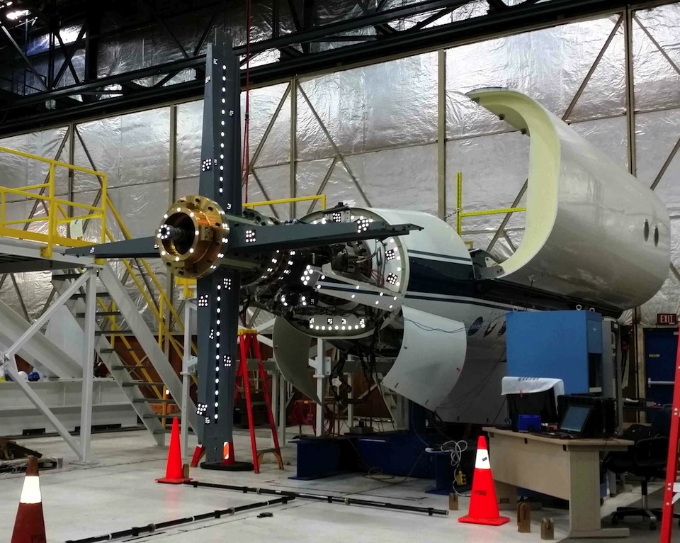
TTR with rotor calibration hardware set up for V-STARS photogrammetry. The white the dots are reference points for deflection measurements. Photo Jan. 2014
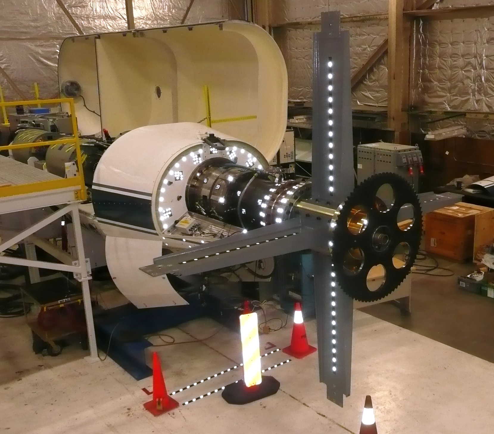
TTR with rotor calibration hardware. The gray arms apply moments, and the black sprocket applies torque. Photo Nov. 2013
TTR being installed in the calibration rig. Photo Oct. 2014
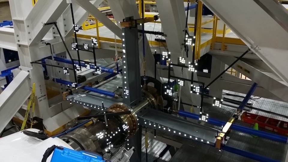
Calibration load hardware, with photogrammetry retroreflective targets (white dots). Photo April 2015.
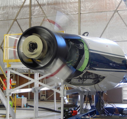
TTR spin test with dummy blade grips (silver with red stripes) to check rotor controls and instrumentation. December, 2016
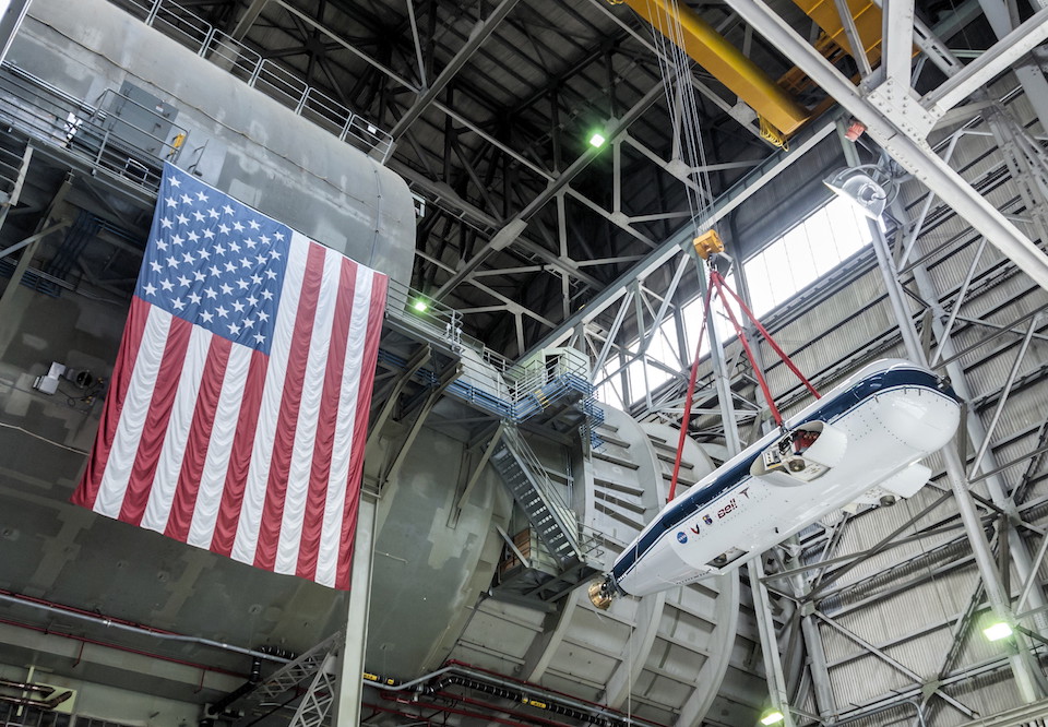
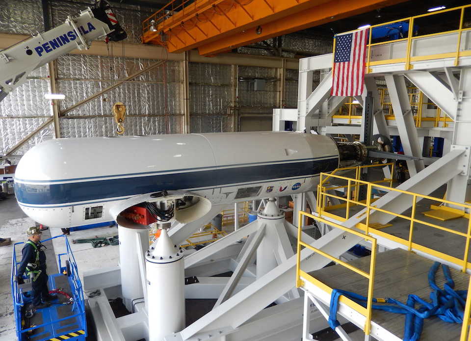
TTR installation into the wind tunnel: hoisting the rig from the NFAC High Bay. The test section is behind the flag. Photo March 2017.
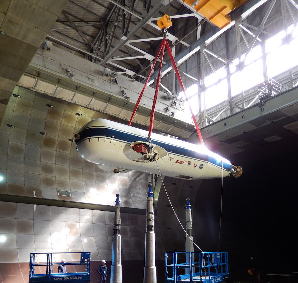
TTR installation into the wind tunnel: lowering the rig into the test section. Photo March 2017.
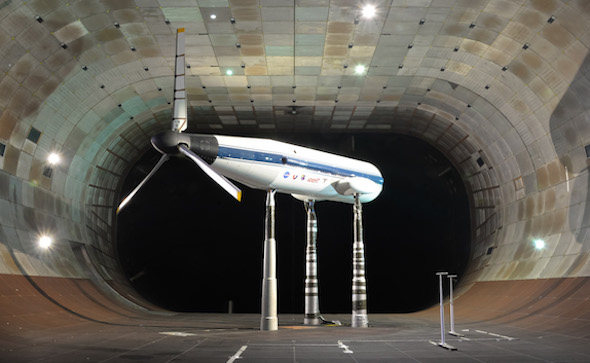
TTR in the NFAC 40 x 80 foot test section: airplane mode orientation. Photo September 2017.
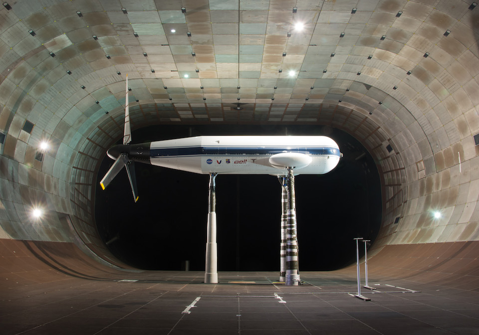
TTR in the NFAC 40 x 80 foot test section: conversion mode orientation. Photo September 2017.
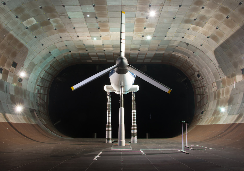
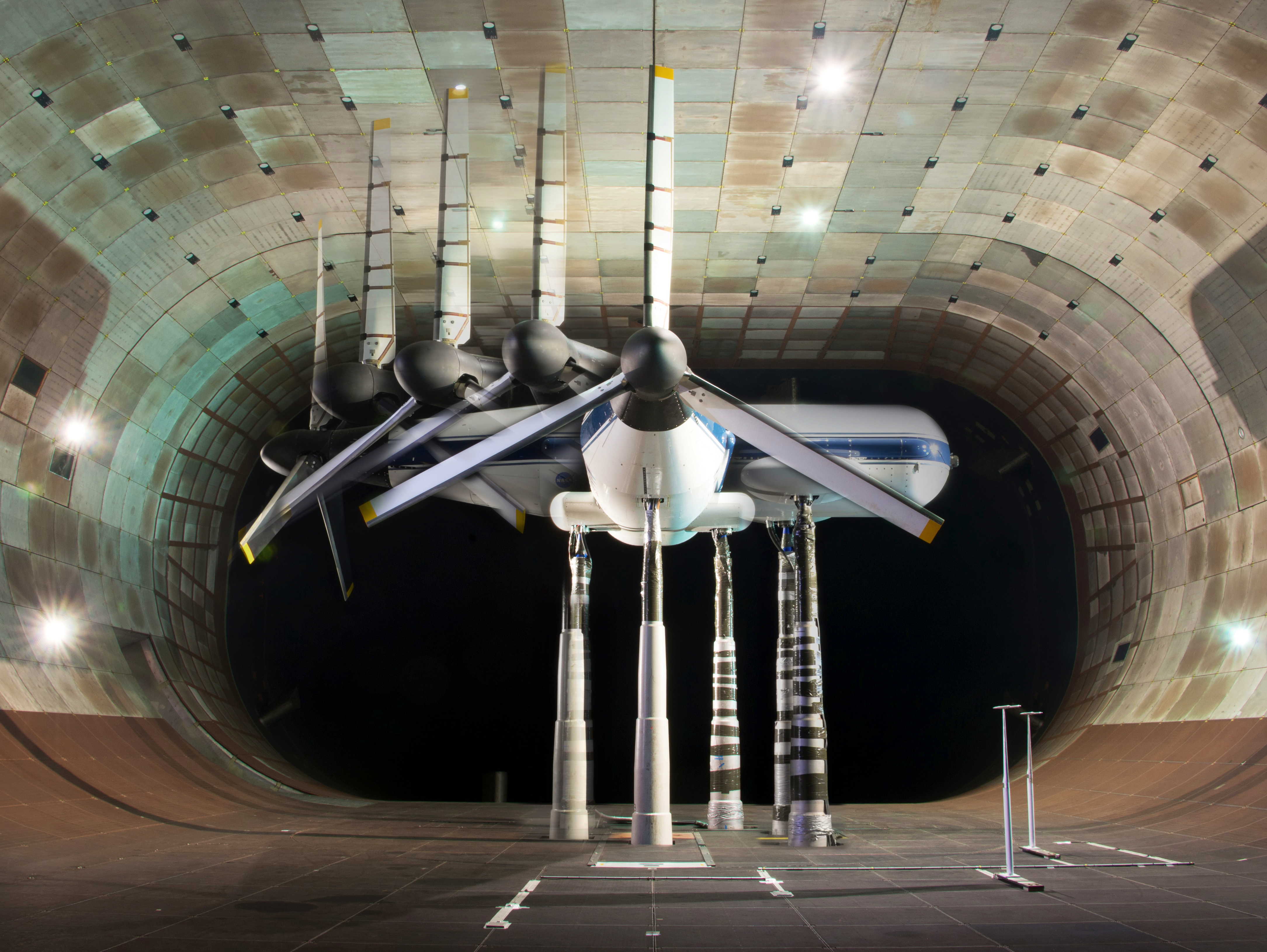
TTR in the NFAC 40 x 80 foot test section: helicopter mode orientation. Photo September 2017.
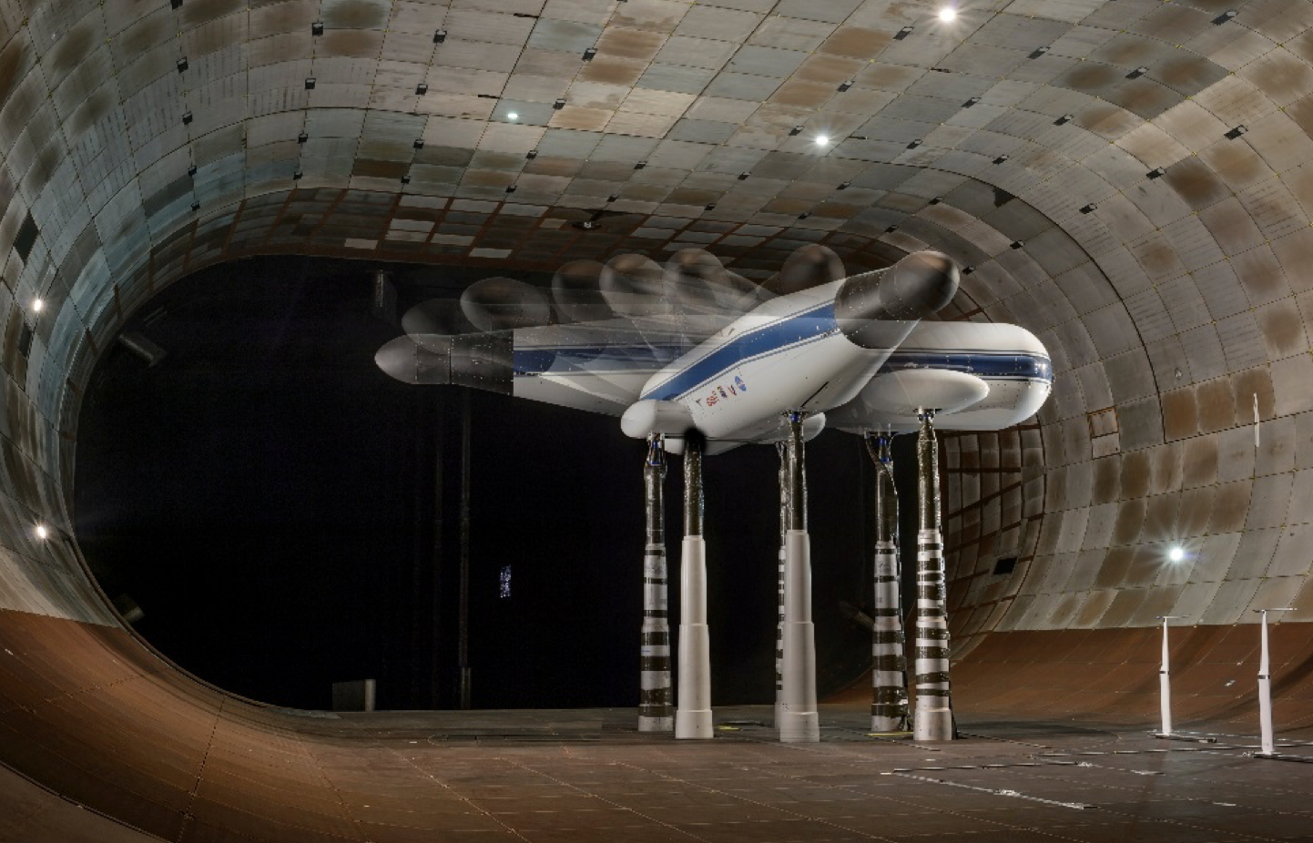
The TTR rotates on the test section turntable to change the angle of airflow ("angle of attack"). Photo Oct. 2017.
TTR configured for aerodynamic tares (no rotor, closed spinner).
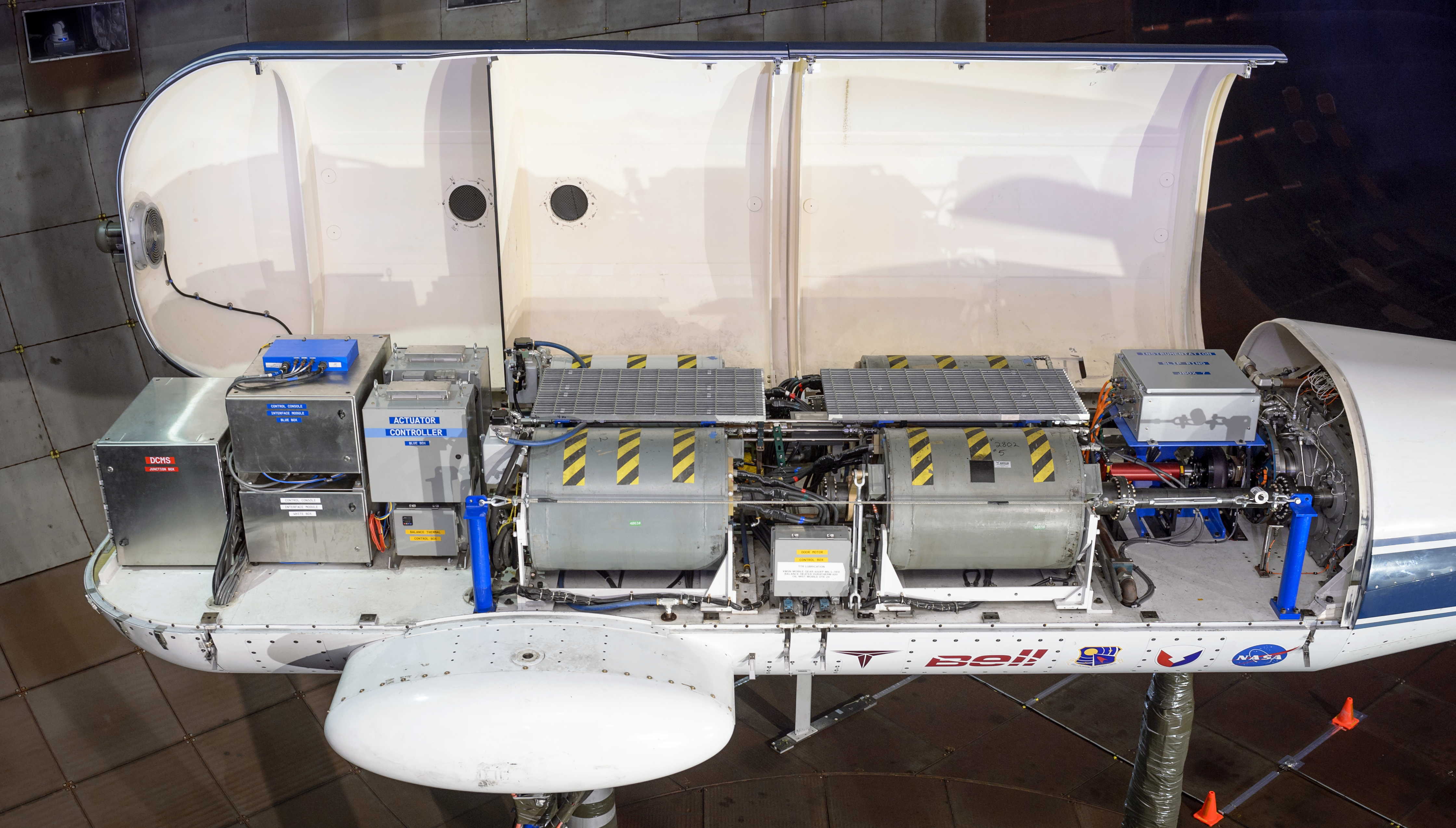
TTR internal components. Gray cylinders with warning stripes are drive motors. Photo Oct. 2018.
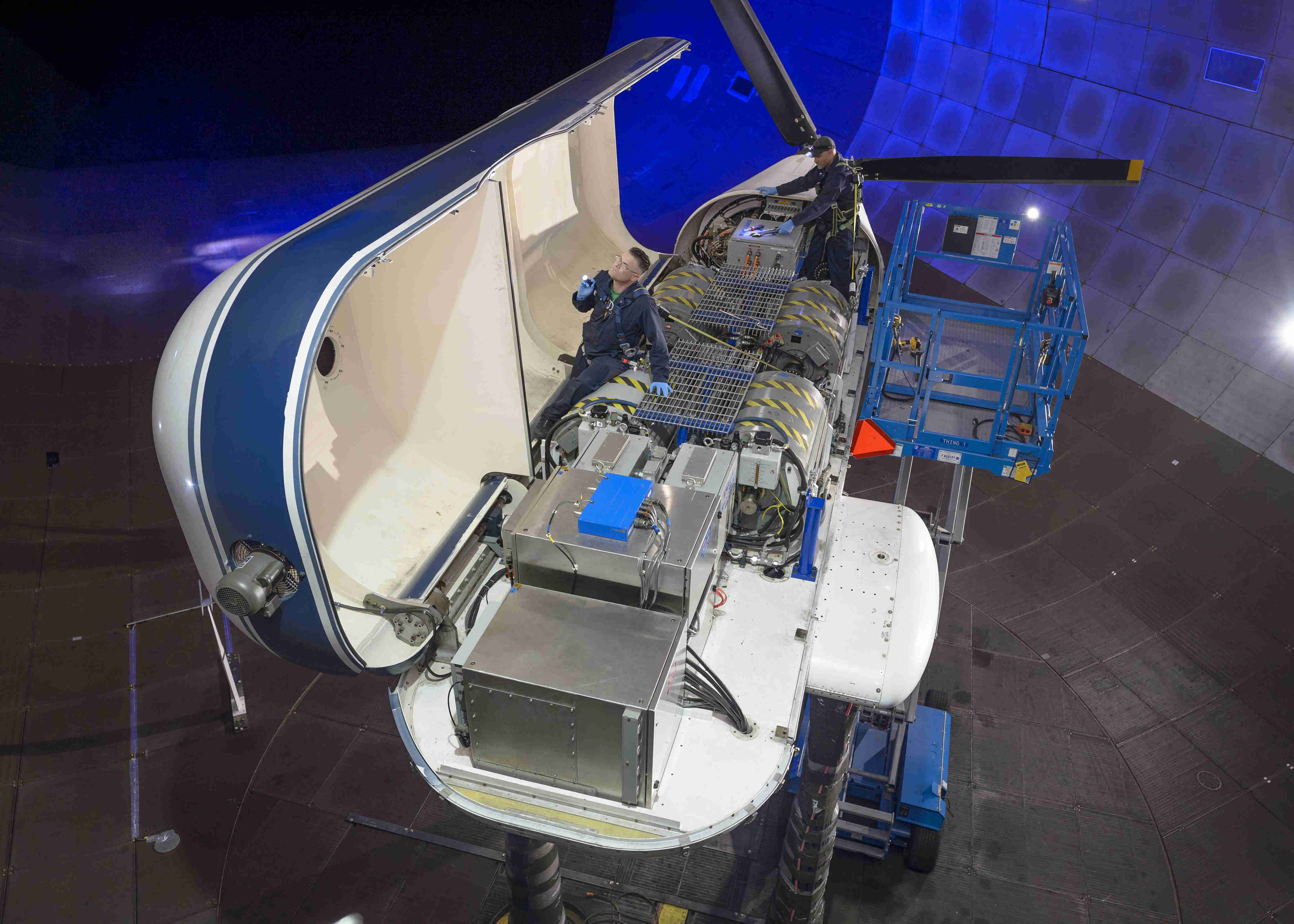
NFAC mechanics inspecting the TTR in the test section. Photo Oct. 2018.
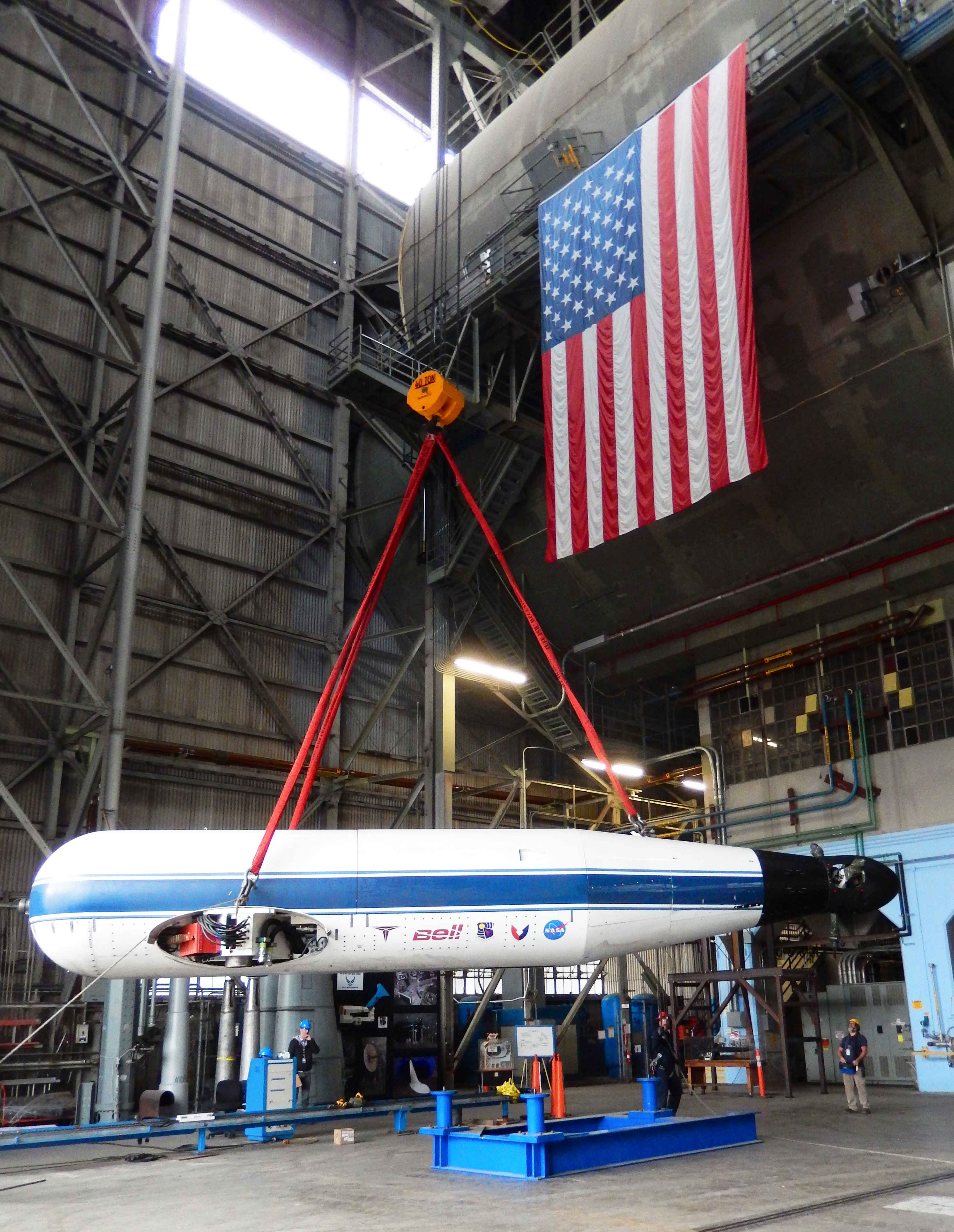
TTR removal from test section. Photo Nov. 2018.